Alternatives to potentiometers - hall sensors, etc

Re: Alternatives to potentiometers - hall sensors, etc

Postby SC-Maik » Fri May 01, 2015 1:27 pm

Who is kind enough to double check this board for me?

Image

Image

For use with 3 wire mode

Image

https://youtu.be/Dwc4hFgNP5I?t=128
SC-Maik
 
Posts: 142
Joined: Tue Mar 03, 2015 3:20 pm

Re: Alternatives to potentiometers - hall sensors, etc

Postby SC-Maik » Mon May 11, 2015 6:14 am

Above custom boards arrived today. I should have first results be tomorrow.

Stay tuned!
SC-Maik
 
Posts: 142
Joined: Tue Mar 03, 2015 3:20 pm

Re: Alternatives to potentiometers - hall sensors, etc

Postby zdayton » Tue May 12, 2015 5:35 am

Just finished soldering mine.

Image

And arms coming off the press soon.

Image
zdayton
Site Admin
 
Posts: 81
Joined: Wed Dec 24, 2014 6:20 am

Re: Alternatives to potentiometers - hall sensors, etc

Postby SC-Maik » Tue May 12, 2015 7:49 am

What kind of connector are you going to use to mount the boards?
SC-Maik
 
Posts: 142
Joined: Tue Mar 03, 2015 3:20 pm

Re: Alternatives to potentiometers - hall sensors, etc

Postby SC-Maik » Tue May 12, 2015 11:11 am

Here is my version for AMS AS5600

Image
SC-Maik
 
Posts: 142
Joined: Tue Mar 03, 2015 3:20 pm

Re: Alternatives to potentiometers - hall sensors, etc

Postby jeruw » Tue May 12, 2015 2:57 pm

Both looking fantastic! I haven't gotten to testing my sensors yet. SC-Maik, how much did your custom boards run? Would you be interested in sharing the schematic? I'd sort of like to try the 4 wire mode, but honestly the 3 wire is probably all we'd need. I don't know how much benefit there would be to being able to calibrate on-demand. I couldn't tell off hand if your board layout would work by default for 5v or if I'd have to tweak it? I need to review it again.
jeruw
 
Posts: 80
Joined: Tue Feb 17, 2015 3:10 pm

Re: Alternatives to potentiometers - hall sensors, etc

Postby SC-Maik » Tue May 12, 2015 3:46 pm

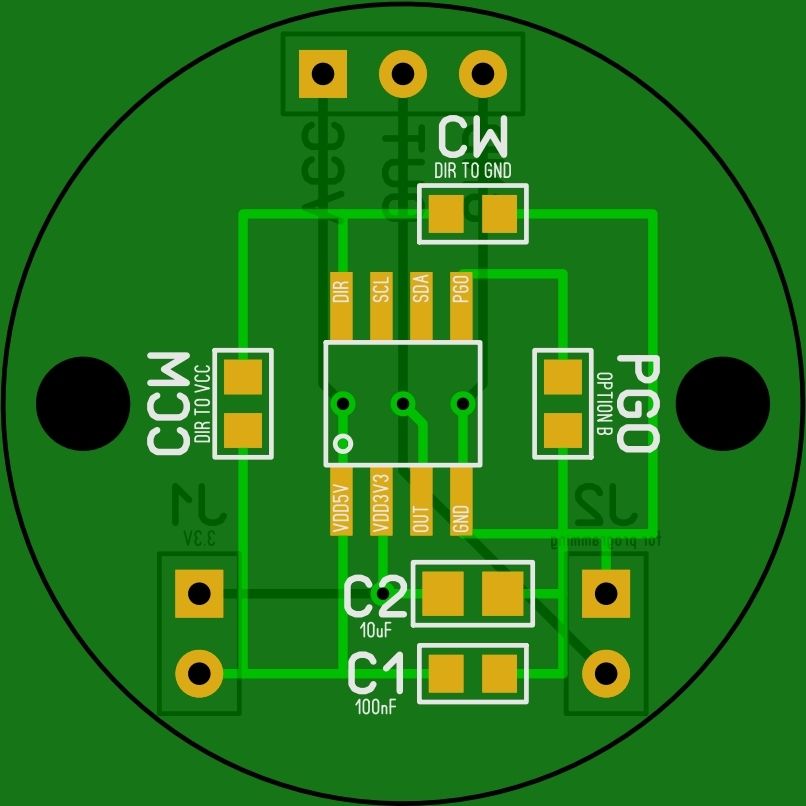
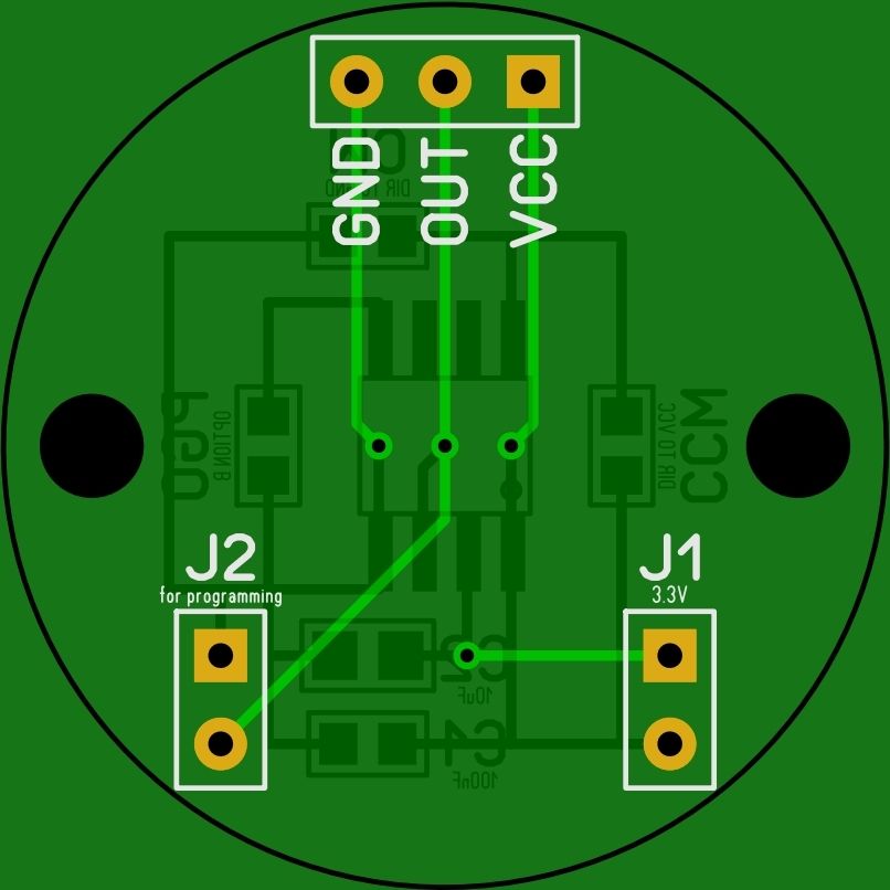
jeruw wrote:Both looking fantastic! I haven't gotten to testing my sensors yet. SC-Maik, how much did your custom boards run? Would you be interested in sharing the schematic? I'd sort of like to try the 4 wire mode, but honestly the 3 wire is probably all we'd need. I don't know how much benefit there would be to being able to calibrate on-demand. I couldn't tell off hand if your board layout would work by default for 5v or if I'd have to tweak it? I need to review it again.


First off all, it works!

I've got myself a 5V Pro Micro, so I am testing it with 5 volts atm. In order to work with 3.3V you have to solder a zero Ohm resistor at R1 (or a jumper wire).

It can be calibrated on demand, using a jumper on J1 (or a switch).
Press throttle all the way down and place the jumper (or press a switch) for a second. That sets min position (0 volts). Take off jumper.
Pull throttle all the way up, place the jumper again for a second. That sets max position (5 volts). Take off jumper.
Calibrated!
Plan is to connect one common switch to all three boards, so I can calibrate all sensors at once.

I am missing 2 things to assemble my throttle. 3D printed pcb holder and actobotic part to keep it in place. I should have them next week.

Five (5) boards (2 layer/1.6 thickness/ Lead free) cost me 29$ plus shipping from PCBway.com.
DON'T choose DHL Express if you plan ordering from them. Shipping is too high (25-30$) and you will probably have to pay custom taxes as well.

I will upload schematic later tonight.
SC-Maik
 
Posts: 142
Joined: Tue Mar 03, 2015 3:20 pm

Re: Alternatives to potentiometers - hall sensors, etc

Postby jeruw » Tue May 12, 2015 4:08 pm

How do you plan to wire the jumper up for a common switch? Would that be a permanent fixture or something you'd plug in for calibration then remove?

My thought for a board was to use the 4 wire 12c mode so that programing could be done without a mechanical switch. You could add the calibration code to the Arduino sketch and use a button mode to trigger the calibration sequence. Enter programming mode, push throttle down, press button, pull throttle up, press button, then it would exit programming mode. I'd use a 4 pin 90 degree connector so my wires could go straight down toward the base and be as low profile as possible. Then possibly put a shroud of some kind over the whole assembly to protect the PCB and wiring. For mounting the PCB I'd considered 2 or 3 holes in the PCB with threaded studs drilled and mounted in my upright. The PCB would mount directly to the upright centered over the shaft position. These could be female threaded studs that you'd screw the board to, or possibly male threaded rod with a nut threaded on to allow for some variation in alignment of the board - not sure if that's necessary.
jeruw
 
Posts: 80
Joined: Tue Feb 17, 2015 3:10 pm

Re: Alternatives to potentiometers - hall sensors, etc

Postby SC-Maik » Tue May 12, 2015 5:21 pm

I was damn wrong and I had to find that out the hard way...

You can program AS5600 on 3 wire more only ONCE, the first time you plug it in with PGO enabled.

I've missed the small letters

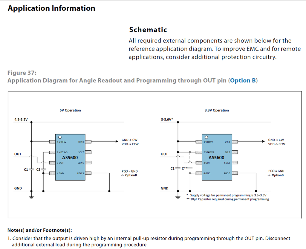
Note(s) and/or Footnote(s):
1. After step 5 the new setting is effective at the output.
2. If step 3 is not followed by step 5 no permanent write will be performed.
3. It is highly recommended to perform a functional test after the procedure.
4. This procedure can be executed only one time; the zero position and maximum angle can be reprogrammed only through the I²C (Option A).
5. This procedure can be executed only if the presence of the magnet is detected (MD = 1).


Jeruw, as it seems your plan to use I2C mode is the best way to do it.
Back to my pcb drawing board...
SC-Maik
 
Posts: 142
Joined: Tue Mar 03, 2015 3:20 pm

Re: Alternatives to potentiometers - hall sensors, etc

Postby jeruw » Tue May 12, 2015 5:38 pm

Ouch! That's unfortunate. It's strange to me that that is only a one time operation.
jeruw
 
Posts: 80
Joined: Tue Feb 17, 2015 3:10 pm

PreviousNext

Return to Discussion

Who is online

Users browsing this forum: No registered users and 1 guest

cron