Throttle geometry

Throttle geometry

Postby SC-Maik » Sun May 17, 2015 5:29 pm

After doing zillion redesigns, I've noticed the following lines in arduino code

//Geometry
float handle_rad = 1.75; // end effector
float base_rad = 1.75; // base
float pushrod_lng = 3.5;
float pivot_lng = 2.25;


From what I can understand, base_rad is the radius of the circle that the three pivot arms create while at 90 degrees.

Image

If I am wrong and base_rad is the the radius of the circle that the three pivot arms create while at 60 degrees (neutral position), why handle_rad has the same value (1.75in)?

Also pivot arm actual length is 2.175in, while pivot_lng is set to 2.25in.
SC-Maik
 
Posts: 142
Joined: Tue Mar 03, 2015 3:20 pm

Re: Throttle geometry

Postby mike43110 » Mon May 18, 2015 2:03 pm

Try the proper values and see the behaviour change.

I will take a look at the code later today/tomorrow and compare it with my textbook - this is after all just a delta manipulator.

Handle_rad should be the radius of the circle which the connecting rods at the top make i.e. the bottom and the top circle.

If the values are incorrect the forward kinematics will be incorrect and this will cause undefined behaviour - the position the arm is in according to the sensors and reality will differ.
Forward kinematics have to be as close to correct as possible.
mike43110
 
Posts: 21
Joined: Fri Apr 24, 2015 11:45 pm

Re: Throttle geometry

Postby SC-Maik » Mon May 18, 2015 10:33 pm

I will change values and report back.

Check picture below as well please

Image
SC-Maik
 
Posts: 142
Joined: Tue Mar 03, 2015 3:20 pm

Re: Throttle geometry

Postby mike43110 » Tue May 19, 2015 11:46 am

Ok!
I read through the code and checked on everything I could.
So, importantly for me the values don't need to be in inches! Just input it in centimeters or millimetres and change gain appropriately i.e. roughly 10 for mm, 100 for cm and 150 for in. Though you can also get away with a gain of 1, it just makes the mapping a little less pretty.

So what I would do is comment out the lines constraining xVal, y and z and then look at the raw numbers before being constrained i.e. debug mode.
Of course this is after having the numbers correct.
The reason why is that your gain probably will need to change. Constrain is just an upper and lower bound for the values. That means that your extremities may not necessarily be defined as the constrain function is limiting them! Once you have found your optimum gain value you can put the constrain back in. I recommend that the gain has you maxing out just before the limitations or to wherever you feel it is the most comfortable remembering that longer travel = more accuracy.

I think that's all I wanted to say? I want to redesign the arms to use tension springs for centring similar to the joystick I am designing - tension springs are easier to source and I can get a FAR stronger centring force.
mike43110
 
Posts: 21
Joined: Fri Apr 24, 2015 11:45 pm

Re: Throttle geometry

Postby SC-Maik » Wed May 20, 2015 9:34 am

Thank you for the time spent to review code and giving your feedback. Very helpful comments.

Hopefully I will put those to a test this weekend once last actobotic parts arrive to mount AS5600 sensors.

mike43110 wrote:I recommend that the gain has you maxing out just before the limitations or to wherever you feel it is the most comfortable remembering that longer travel = more accuracy.


Regarding above comment, I have to add that on my first build (with pots) I have noticed values x/y/z maxing out before throttle physically reach it's end limits. I had about 15-20 more millimeters of traveling distance to spare on each axis, which personaly I don't want to.

mike43110 wrote:I want to redesign the arms to use tension springs for centring similar to the joystick I am designing - tension springs are easier to source and I can get a FAR stronger centring force.


Yeah! More reasons to continue redesigning! I don't want to finish my throttle, I want to keep modding it :)

Another idea I had is to add "something" to give me some extra resistance (physical feedback) near throttle traveling limits. When I reach those limits and keep pushing/pulling to have ship boost activating.
SC-Maik
 
Posts: 142
Joined: Tue Mar 03, 2015 3:20 pm

Re: Throttle geometry

Postby mike43110 » Thu May 21, 2015 3:52 am

I am done with the gimbal of the joystick. Now off to give it a shell and a handle! Z-axis twist is a little painful to do the way I want to as it makes for quite a large palm rest (depending on spring size selected of course). I think I will get a feel first for the right dimensions on the stick then move it over to the delta once sorted.

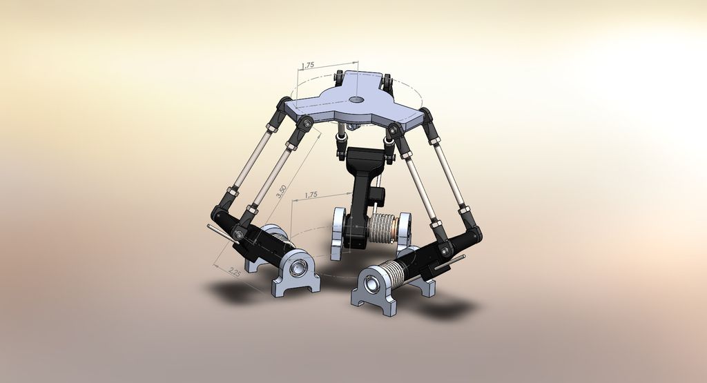
ALTHOUGH - I will get started on redrawing the delta soon. I am making my own bearing pillow-blocks as I want to have the tension springs mounted on the pillow blocks. I still need to decide if they should be 4DOF or 5DOF restricted when inserting. The pillow blocks will all have an extra say 20mm piece added onto it for mounting purposes. I plan to have that on the stick and throttle. I will need to make sure my printer is set up very well before printing of course!
Thanks for pointing this stuff out though. I may have forgotten it myself and had to waste time looking for it! I did a BEng and now am doing an MSc in Comp. Sci. so code is my thing. These kind of things are my speciality in fact. So it was actually fun to go and look through the code.

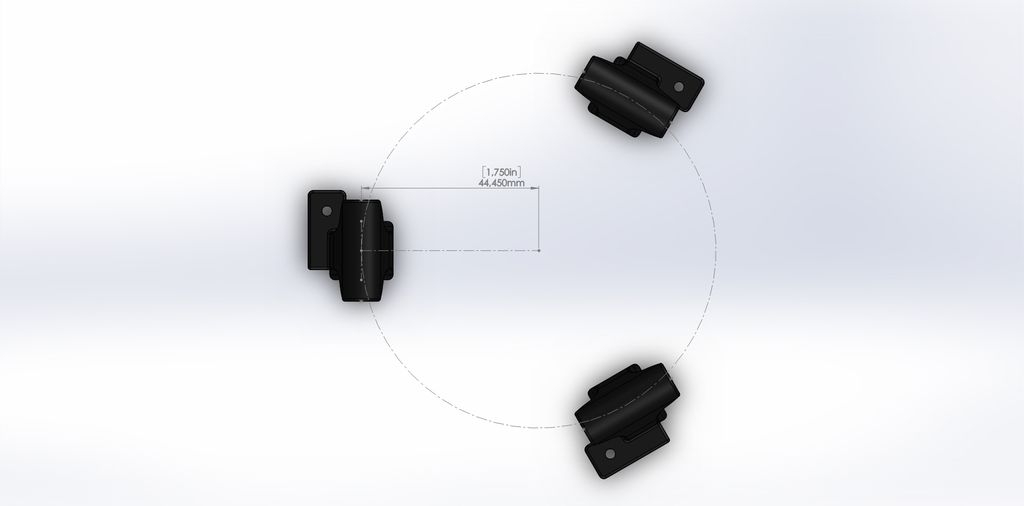
I need to make my pillow block which holds the pivot arm at 60 degrees still... Not difficult. Just want to do it in a way that is space efficiently.

I have an idea on those limits! If you extend the bottom of the pivot arm, you can place physical limits on the throttle by mounting a switch. That would get you the feedback desired! It could swing into a small compression spring that activates a button or it could just hit against the button requiring you to give it a little oomph to press it. A 5N switch should suffice along with a decent centring force.

It is too fun to keep modding this! I am waiting for all my parts to arrive before I can start my own build but I am trying to fix the things I would personally dislike for myself. I wouldn't want the boost on the limits for example. I plan on using a thumb button for that. I plan on having a throttle slider too on the thumb so I can make smart use of the strafing capabilities of the delta in combination with the match speed command.
When I fly my hull B I won't need the Delta until I do a landing. Then I may kiss it when done :D I don't know how agile it will be when empty. I can't imagine it being anything nice when full!
mike43110
 
Posts: 21
Joined: Fri Apr 24, 2015 11:45 pm

Re: Throttle geometry

Postby SC-Maik » Fri May 22, 2015 6:01 am

mike43110 wrote:When I fly my hull B I won't need the Delta until I do a landing. Then I may kiss it when done :D I don't know how agile it will be when empty. I can't imagine it being anything nice when full!


You just found yourself an escort pilot :)
SC-Maik
 
Posts: 142
Joined: Tue Mar 03, 2015 3:20 pm

Re: Throttle geometry

Postby mike43110 » Fri May 22, 2015 6:37 am

SC-Maik wrote:
mike43110 wrote:When I fly my hull B I won't need the Delta until I do a landing. Then I may kiss it when done :D I don't know how agile it will be when empty. I can't imagine it being anything nice when full!


You just found yourself an escort pilot :)


Haha, can make a delta only squad! Looking forward to hearing how everything compares.
mike43110
 
Posts: 21
Joined: Fri Apr 24, 2015 11:45 pm

Re: Throttle geometry

Postby SC-Maik » Fri May 22, 2015 7:26 am

We can start by making a Raidcall/Ventrilo/TS3 channel
SC-Maik
 
Posts: 142
Joined: Tue Mar 03, 2015 3:20 pm

Re: Throttle geometry

Postby Ghostpilot » Sat Aug 15, 2015 8:12 am

SC-Maik wrote:I will change values and report back.
So what was the result after setting the pivot length to the actual length of the pivot arm?
Any changes in response or sensitivity?
Ghostpilot
 
Posts: 54
Joined: Sun Aug 09, 2015 5:48 pm

Next

Return to Discussion

Who is online

Users browsing this forum: No registered users and 1 guest

cron